
| TECHNICAL SPECIFICATIONS SINGLE PHASE STABILIZER | |
|---|---|
| INPUT | |
| Input Voltage Regulation Range | 160 – 250 Vac (1 Phase) |
| Operating Frequency | 50 / 60 Hz ±10% |
| System Input Protection | Over Current MCB, Surge Arrestor (Optional) |
| OUTPUT | |
| Voltage | 220 / 223 / 240 V AC |
| Regulation Speed | 50 – 60V per Second |
| Frequency | 50 and 60 Hz |
| Protection | Short Circuit, Over Current, Over and Under Voltage |
| TRANSFORMER | |
| Material | 100% Copper |
| Efficiency | 90% Plus |
| Mechanical By-pass | Manually Controlled Line |
| Protection Level | IP 20 (IP54 is Optional) |
| Cooling | Natural Cooling |
| GENERAL ENVIRONMENT | |
| Operating Temperature | -10 ºC —-+40 ºC |
| Storage Temperature | -25 ºC —-+60 ºC |
| Relative Humidity | Less Than 90% |
| Working Altitude | Max 3.000 Meter |
| Acoustic Noise | Max 60 Db |

| TECHNICAL SPECIFICATIONS THREE PHASE STABILIZER (10 TO 150kva) | |
|---|---|
| INPUT | |
| Input Voltage Regulation Range | 270 – 435 Vac (3 Phase) |
| Operating Frequency | 50 / 60 Hz ±10% |
| System Input Protection | Over Current MCB, Surge Arrestor (Optional) |
| OUTPUT | |
| Voltage | 380 / 400 / C415 Vac |
| Regulation Speed | 50 – 60V per Second |
| Frequency | 50 and 60 Hz |
| Protection | Short Circuit, Over Current, Over and Under Voltage |
| TRANSFORMER | |
| Material | 100% Copper |
| Efficiency | 90% |
| Mechanical By-pass | Manually Controlled Line |
| Protection Level | IP 20 (IP54 is Optional) |
| Cooling | Natural Cooling |
| GENERAL ENVIRONMENT | |
| Operating Temperature | -10 ºC —-+40 ºC |
| Storage Temperature | -25 ºC —-+60 ºC |
| Relative Humidity | Less Than 90% |
| Working Altitude | Max 3.000 Meter |
| Acoustic Noise | Max 60 Db |


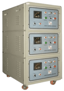
Single Phase: 5 – 25 KVA Servo Voltage Stabilizer
Three Phase: 10 – 250 KVA Servo Voltage Stabilizer

In this modern technological world, we are completely dependent on electronic and other tools for survival. The imbalance between abundant demand and irregular supply has widened day by day, making it one of the most complex problems in today’s world. E.T.E.S has found the solutions to these challenges and proudly serves as one of the most trusted Servo Voltage Stabilizer manufacturers in Pakistan.
Our production, testing, and final inspections are carried out with special care to ensure quality and reliability. The product is guaranteed for one (1) year if used according to the guidelines stated in the user’s manual. However, maintenance and part replacements caused by unauthorized modifications or the use of non-original parts are not covered under the warranty.

We highly recommend reading the user manual carefully and following all warnings and precautions to achieve maximum efficiency from the machine. We appreciate your trust in our product and hope that it serves you reliably for many years to come.

In standard Models;
Single Phase: 160/250V input (±2% tolerance), regulated output
Three Phase: 275/450V input (±2% tolerance), regulated output
Output tolerance can be modified as per requirements.

A Servo Controlled Voltage Stabilizer consists of a toroidal transformer (variable transformer), an assistant transformer, and electronic circuits that control the changing transformer.
With a fast-response control system, a high-starting torque DC motor, and an efficient regulation mechanism, it quickly stabilizes minor voltage fluctuations. The servo motor is automatically deactivated by limit switches when it exceeds operational limits, and the control circuit ensures that the output voltage is adjusted to the desired value.
Once the regulation is complete, the motor’s power is cut off by an electronic braking circuit, allowing the stabilizer to operate silently and efficiently.
Voltage stabilizer is affected by no phase cuts as the phases in tree phase voltage stabilizers are produced separately. As the voltage stabilizers are produced as KVA and VA, count the expenses of the device to which you will attach the voltage stabilizer as KVA and VA. If needed, call our company for information.

Before putting the voltage stabilizer into service, ensure that all connected devices are turned off. Once the stabilizer is operating normally, you can safely turn on your devices.
Use the upper section of the cable you choose as the connection cable to minimize line losses. Before operating your voltage stabilizer with an attached device, set the main switch on your device to the 0 (zero) position. Also, turn the automatic switches (W automat) to the 0 position (which means it is off when the handle is downward).
To activate your voltage stabilizer, first turn the W automat to the up position (for small power loads) and set it to I position. Then, turn the Main switch of the stabilizer to 2 (two) position (as shown in Picture 1-2). This will put the voltage stabilizer into service.
If you wish to switch from the voltage stabilizer to city power, turn the Main switch to position I (one) – NETWORK. For small power loads, turn the handle of the automatic fuses downward to the 0 position. This will take the stabilizer out of service, allowing you to use city power instead.
If your voltage stabilizer is not functioning properly, check whether the city voltage has exceeded the stabilizer’s adjustment capacity.
You can see the city current in the VOLTMETER by turning the MAIN switch to NETWORK position. If your voltage stabilizer is giving disorderly voltage while the city current is inside the voltage capacity of your voltage stabilizer, check the fuses on it. While doing this, turn the voltage stabilizer to NETWORK position and turn the W automate fuses downwards.
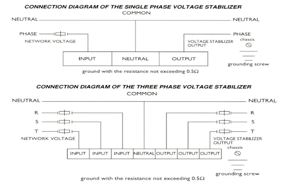
The switch with turn on-off handled on the upper part of the 2 units of three phase handled switches on your voltage stabilizer is the switch that conveys the voltage coming from the network to the bobbin and variable transformer part of the voltage stabilizer. The inverse handled switch on the below part, connects the output of the voltage stabilizer to network or voltage stabilizer output whenever needed. Both switches’ handle shall be downwards position to connect directly to city current. Both switches’ handle shall be upwards to connect to voltage stabilizer’s current.
If you don’t have the possibility of tracking the operation of your voltage stabilizer (daily voltages should be checked from the voltmeter once) you should buy one with a protective unit. If your voltage stabilizer has protective unit to high voltage and phase, when your voltage stabilizer outputs high or low voltage because of an/problem, current is cut and if the voltage gets into order it starts operating automatically. If protective unit is not getting into service that means the problem continues. So as not to be left without energy, you can operate your voltage stabilizer by eliminating High Voltage Protection switch and protective unit on your voltage stabilizer. When one of your phases are cut protective unit will be out of service. It won’t come back until the phase is back; if you want to use it with two phases you can connect your voltage stabilizer to network directly.
You can get information from our company when needed.
Our voltage stabilizers are guaranteed against production malfunctions for 1 (one) year from the date of the
receipt.
PDF Link Here : Download AC Voltage Regulator Brochure


