
These Rectifier units are suitable for all electro deposition processes within their rating. The widest applications
in the field require maximum voltage of 8V, 12V and 20V D.C. at various current capacities as per requirement.
A range of current ratings from 100 amps to 10000 amps is covered in our regular manufacture. Our standard
sizes are listed in the price list issued separately.
Input Voltage: 360 to 440V A.C. 3 Phase 50 Hz 4 Wires
Output Voltage: Continuously variable from zero to the full rated D.C. voltage
Output Current: From zero to Rated maximum D.C. Current
Efficiency: Above 80%
Temperature Rise: Less than 45°C above ambient at the top of the oil.
‘ETES’ make Electroplating Rectifier units are designed for three phase, 50Hz. AC input supply and are suitable
for operation at any voltage between 360 to 440 volts. Thus, it covers a wider range to cater for mains voltage
fluctuations. The input to the unit is to be connected through a MCCB & fuse unit of proper rating, which is not
included in the scope of the supply and has to be procured separately.
The D. C. output is continuously and sleeplessly variable from zero to the full rated voltage for any input voltage
between 360 to 440 volts and for any load between zero to its rated full load. The ripple content in the output is
very low (approximately 5%) and as such these units are very much suitable for all special processes such as chrome plating or hard chrome plating where low ripple content is necessary.
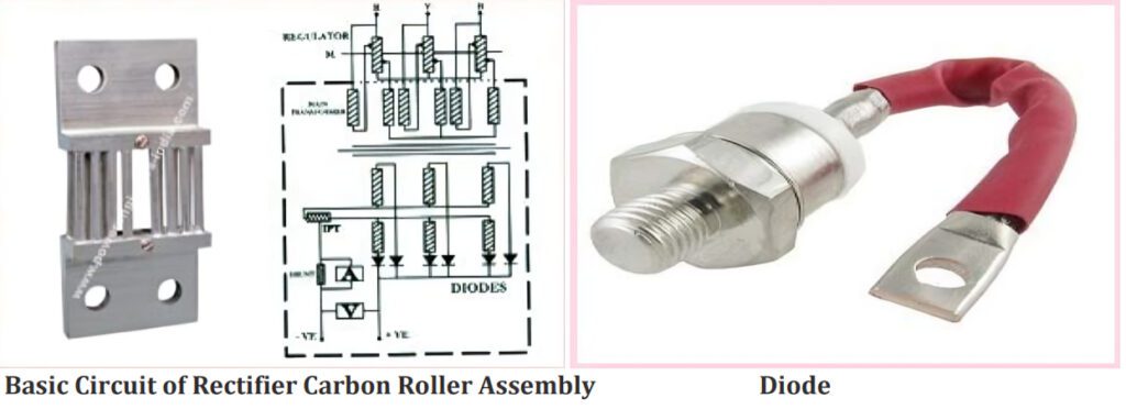
The circuit employed in these rectifier units is simple and universal. Supply is given to Rectifier stat (continuously variable voltage auto transformer), which in turn supplies a variable voltage to the primary of a three phase double wound Delta / Double star connected transformer through H. R. C. fuses. The secondary of the transformer is connected to Hexa-phase connected rectifier using Silicon Diodes. The output is obtained from the rectifier and the star points of the transformer through an inter phase transformer. Moving Coil voltmeter and ammeter with shunt are provided to measure the output voltage and output current.
Output is an important factor in Electrode position processes. ‘ETES’ provide a step less and continuous variation of output voltage, which is a far superior method to other methods of control like resistance boards, tap switches etc. The step less variation is achieved with the help of Rectifier stat for Continuously Variable Voltage Auto Transformer manufactured by ‘ETES’. Unlike other methods of output control, Rectifier stat provides a step less, on-load and without break variation of output Voltage, without any loss of power. It being one of our own standard products, availability of spares or replacement is guaranteed, although the necessity is very rare.
Overloading or short circuiting is not a rare occasion in Electro deposition processes. Special High Rupturing Capacity (H.R.C.) fuses are therefore provided on the primary of the Main transformer. These fuses will blow only when there is overload or short circuit on the output or if there is an internal short circuit and in such cases they should be replaced by H.R.C. fuses of the same rating only.
This is of conventional design and conforms to standard specifications of regards the temperature rise and insulation are concerned. The primary is delta connected and two secondaries have star connected windings.
The IPT is connected between two star points of the secondary’s of the main transformer; The Inter phase transformer improves commutation thereby increasing the rating of the Rectifier.
These is made up of sturdy liberally rated Silicon diodes and are arranged in a six phase circuit. The diodes are
mounted on cooling fins so as to dissipate the heat thereby increasing the rating of the diode. Depending upon
the output current rating, necessary number of diodes is connected in parallel.
A Voltmeter and an Ammeter are provided on a separate panel to indicate the output voltage and output current. The panel is mounted on one of the tanks to enable easy manipulation with the help of the Rectifier stat. The ammeter is used in conjunction with an external shunt, which is fitted inside the tank.
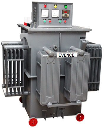
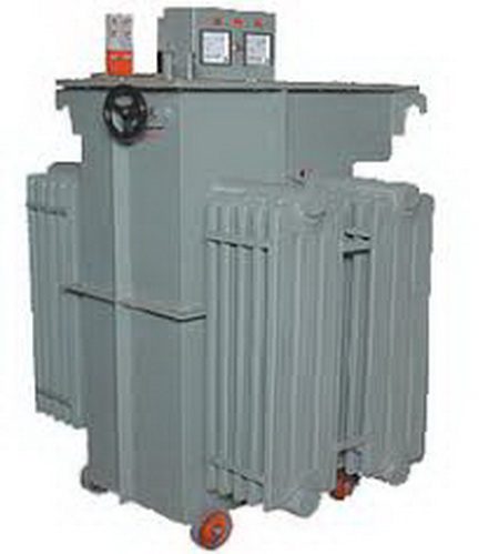
The units are made in natural oil immersed construction. Any Electro deposition process is always associated with acidic and corrosive fumes and dust. Any contact with these fumes and dust obviously reduces the life and reliability of the Rectifier. Oil immersed construction offers best protection to the Rectifier unit in this regard and therefore increases the life enormously.
The Rectifier stat is always housed in separate tank. For rectifier units up to a maximum output capacity of 50KW, the transformer and the rectifier are housed in one single tank. For higher capacities separate tanks for transformer and rectifier are used. For rectifier units of current rating 5000 amperes and above, the rectifier is supplied in Separate tank for better cooling.
If the customer can guarantee that sufficient precaution is taken to see that corrosive fumes and dust do not come in contact with the rectifier unit, we will be pleased to make special offers for units in Air cooled or combined OIL/AIR cooled construction.
The mains supply is to be connected to the Rectifier stat input terminals by a cable of proper size through a switch fuse unit. The cable of same size should be used for connections from Rectifier stat output to the primary of the transformer. If the transformer and rectifier are supplied in more than one tank, the bus bars of proper sizes for interconnection between various tanks are supplied free with the rectifier unit. The output bus bars are brought out, to which the output connections should be made by bus bars of proper size.
The Units can also be supplied for remote control or automatic control of output. For remote control, a separate control panel can be provided to operate the motor of the Rectifier stat by means of push buttons & a Voltmeter & Ammeter to indicate the output voltage and current. In case of automatic control the customers are requested to specify the mode of control, whether the requirement is for automatic constant voltage or constant current. These will be at an extra cost which will be quoted against specific requirements. Units of ratings beyond our standard specifications, such as input voltage range, maximum output voltage and current or with overload requirements of short duration can also be quoted against specific enquiries.
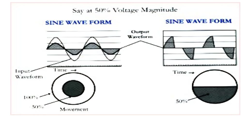
The function of the variable output controls is to control the voltage or current or its operating range by varying input voltage to the main transformer primary. The DC output voltage variation is achieved step lessly 0-100% by means of an On Load roller type power make voltage regulator.
| Advantages of Power’s Make Roller Type Regulator vs. Conventional Make Rectifier | |
|---|---|
| Roller Type Regulator | Conventional Make |
| No waveform distortion at any load, Electrical wave is like a moving wheel. For 50% Rated Voltage, the diameter of the wheel is reduced accordingly, i.e., magnitude for a wave is decreased. | Waveform distortion in thyristor type; it is like cutting the wheel by 50% and then moving the wheel, meaning the wave is cut but shown at full magnitude. |
| Higher power factor of more than 98 is achieved. | The power factor is lower, between 0.5 to 0.75. |
| The system is simple and can be repaired and maintained even by a simple mechanic. | The system is specialized and requires a specially trained electronic engineer for repair and maintenance. |
| The cost of spares is very negligible. | The cost of replacement is very high. |
| Copper section for a particular current is 3 times that of conventional make. | Copper section for a particular current in a conventional make is 1/3. |
| Carbon roller rolls on the coil and has a trouble-free life of more than 20 years. | Carbon brushes slide on the coil, have a shorter life due to sliding on the coil, and break regularly. |
| Overall losses are less. | Overall losses are more. |
PDF Link Here : Download Electroplating & Anodizing Rectifier


